Reverse Engineering a Cypress USB to Serial driver
The last few weeks I have been busy on a solar monitoring project. I have a minimal viable product working based on an RS232 enabled inverter I have here. The first client I wanted to deploy it with has a similar inverter from the same company, just with a usb port instead of RS232. I was expecting it to be a serial over USB port that would just work as-is with a usb to serial driver, especially because it advertises itself as a Cypress USB to Serial device when you attach it to your computer. Unfortunately this wasn’t true, requiring me to reverse-engineer the USB communication for it. In the end this was easier than I thought it would be and it was a whole lot of fun. This post just shares the quest I went through.
The inverter uses a Cypress Serial to USB chip for communication with device ID 0665:5161. This is the lsusb output:
$lsusb -vd 0665:5161

Bus 001 Device 004: ID 0665:5161 Cypress Semiconductor USB to Serial
Couldn't open device, some information will be missing
Device Descriptor:
  bLength                18
  bDescriptorType         1
  bcdUSB               1.10
  bDeviceClass            0 (Defined at Interface level)
  bDeviceSubClass         0
  bDeviceProtocol         0
  bMaxPacketSize0         8
  idVendor           0x0665 Cypress Semiconductor
  idProduct          0x5161 USB to Serial
  bcdDevice            0.02
  iManufacturer           3
  iProduct                1
  iSerial                 0
  bNumConfigurations      1
  Configuration Descriptor:
    bLength                 9
    bDescriptorType         2
    wTotalLength           34
    bNumInterfaces          1
    bConfigurationValue     1
    iConfiguration          0
    bmAttributes         0xa0
      (Bus Powered)
      Remote Wakeup
    MaxPower              100mA
    Interface Descriptor:
      bLength                 9
      bDescriptorType         4
      bInterfaceNumber        0
      bAlternateSetting       0
      bNumEndpoints           1
      bInterfaceClass         3 Human Interface Device
      bInterfaceSubClass      0 No Subclass
      bInterfaceProtocol      0 None
      iInterface              0
        HID Device Descriptor:
          bLength                 9
          bDescriptorType        33
          bcdHID               1.11
          bCountryCode            0 Not supported
          bNumDescriptors         1
          bDescriptorType        34 Report
          wDescriptorLength      27
         Report Descriptors:
           ** UNAVAILABLE **
      Endpoint Descriptor:
        bLength                 7
        bDescriptorType         5
        bEndpointAddress     0x81  EP 1 IN
        bmAttributes            3
          Transfer Type            Interrupt
          Synch Type               None
          Usage Type               Data
        wMaxPacketSize     0x0008  1x 8 bytes
        bInterval              12
There is stock software with this inverter and many other inverters and UPS’s that use the same chip. This software runs on 32 and 64 bit windows, linux and mac, which is already an impressive list. But I need my software to run on an ARM device. The stock software is easy to decompile and gave me a lot of info on the commands the inverter understands. It uses a native platform specific compiled driver through with a JNI interface for it’s usb communication. This one is (as far as I can find) not available for ARM devices.
If you’re not using the supplied driver, the usbhid driver binds to it on Linux, suggesting it is a keyboard or mouse, even though it’s description is a Cypress USB to Serial device. The cypress_m8 driver for linux supports a Cypress USB to Serial devices that manifest itself as HID device. Even though my device is not claimed by that driver, I hoped it might be supported by it nonetheless. Thanks to info on the ubuntu ask stackexchange site I figured out how to add this device ID to the cypress_m8 driver and recompile it, but the driver complained a required endpoint was not available. So no luck there.
The next was going to be reverse engineering the supplied driver. I started looking at this point at the PyUSB module, which is an awesome python interface to the libusb library. It is quite easy to use it to communicate with usb devices in python. The tutorial on it is really good, but left me wondering about how the device would communicate with the control, interrupt, isochronous and bulk messages. Some random tries to communicate with it failed.
To get more info on the communication, i looked at decompiling the supplied driver, which is a whole can of worms that’s definitely not a magic bullet. There’s a few good disassemblers and decompilers available, but they didn’t supply me with any good info beyond what the objdump and strings tools in linux can already give you.
Using objdump I saw a lot of the functions that are in the driver. Googling those function names, it turned out that most of this driver is actually just the regular open source libusb driver (is it even legal for them to publish a closed source driver containing the libusb code?). It just implements a few extra functions around it, and a Java JNI set of functions on top of that. So my pyusb (or any libusb based library for that matter) direction was the right one. I just needed to figure out what those extra functions were doing. Googling one of then (ups_write), I figured out that K3A reverse engineered his UPS based on the same chip already. This was an enormous help, even though it’s only just a few lines of code really. I definitely owe him a Beer over IP. It confirmed that I was heading in the right direction, and he showed me exactly what the ups_write and ups_read functions are doing. Ups_write is sending control messages and ups_read does an interrupt transfer to get the response back. That is really most of what I needed. With this knowledge I could send messages to my inverter and get data back.
The messages for his UPS differ from the ones of my inverter though. I already figured out the messages that these inverters need from the Java code, but it looked like the driver (probably in the Java JNI functions) is translating these messages into something else before sending them to the UPS. So needed to still test the communication between the driver on my pc and the inverter. A complication is that although I have vpn access to the arm box attached to the specific inverter, it is located over an hour drive away from me in a workshop, and the whole problem stated in the first place because their driver doesn’t work on ARM.
Was I going to get in a car and drive there for capturing the communication between the stock software and inverter on my laptop? Of course not! Enter the USB/IP project. They wrote a daemon and driver to allow you to forward usb communication over IP, allowing me to share the inverter’s usb connection from the ARM box, through the VPN to my local laptop, and run the software locally as if it was connected directly to it.
So the now I could use wireshark and usbmon to directly monitor. The steps to take are start wireshark on the usbmon interface. Start capturing and then start the “working” application. Let it go until you feel the application got data through USB that it understands, stop it and stop the capturing in wireshark. At that point you should have some useful USB data. You should filter in wireshark to only see the relevant data. I did it with the filter usb.bus_id == 4, which filters everything on the bus that my device (usbip device) is on. You can check which bus it is on with ‘lsusb’ in linux.
Next you need to see if you can create the same traffic from pyusb. So I opened a second wireshark instance (so I can compare the two side-by-side), started capturing in this one and then started python and setup the usb device there. I used the following code for that:
import usb.core, usb.util, usb.control
import crc16
vendorId = 0x0665
productId = 0x5161
interface = 0
dev = usb.core.find(idVendor=vendorId, idProduct=productId)
if dev.is_kernel_driver_active(interface):
    dev.detach_kernel_driver(interface)
dev.set_interface_altsetting(0,0)
What the vendorID, productID and interface numbers are depends on your device. lsusb -vd <vendorId>:<productID> might give you more info. This is where K3A helped me a lot.
From that point you need to look in wireshark at the USB data going back and forth. As I said I had two windows open, one with the data sent by the program I had (and it’s driver) the other with the data I sent back and forth. If you click on a packet in wireshark, you see two panels with the data being sent. The bottom panel contains the raw hexadecimal and text representations of that data side by side, while the middle one contains the interpretation of that for this protocol. So if you click on a field in the middle panel, it will highlight the hex and text data that correspond to it in the bottom. If you see differences between data between both wireshark windows, you can see that way which USB/URB fields are actually different. There are a few that will always be different, namely the URB id, URB sec and URB usec fields. So don’t worry about those. In my case, when talking USB control requests, the main points to get right where the bmRequestType (0x21 in the example below) bRequest (0x09), wValue (0x0200), wIndex(0x0000), wLength (0x0008) and the actual Data Fragment.
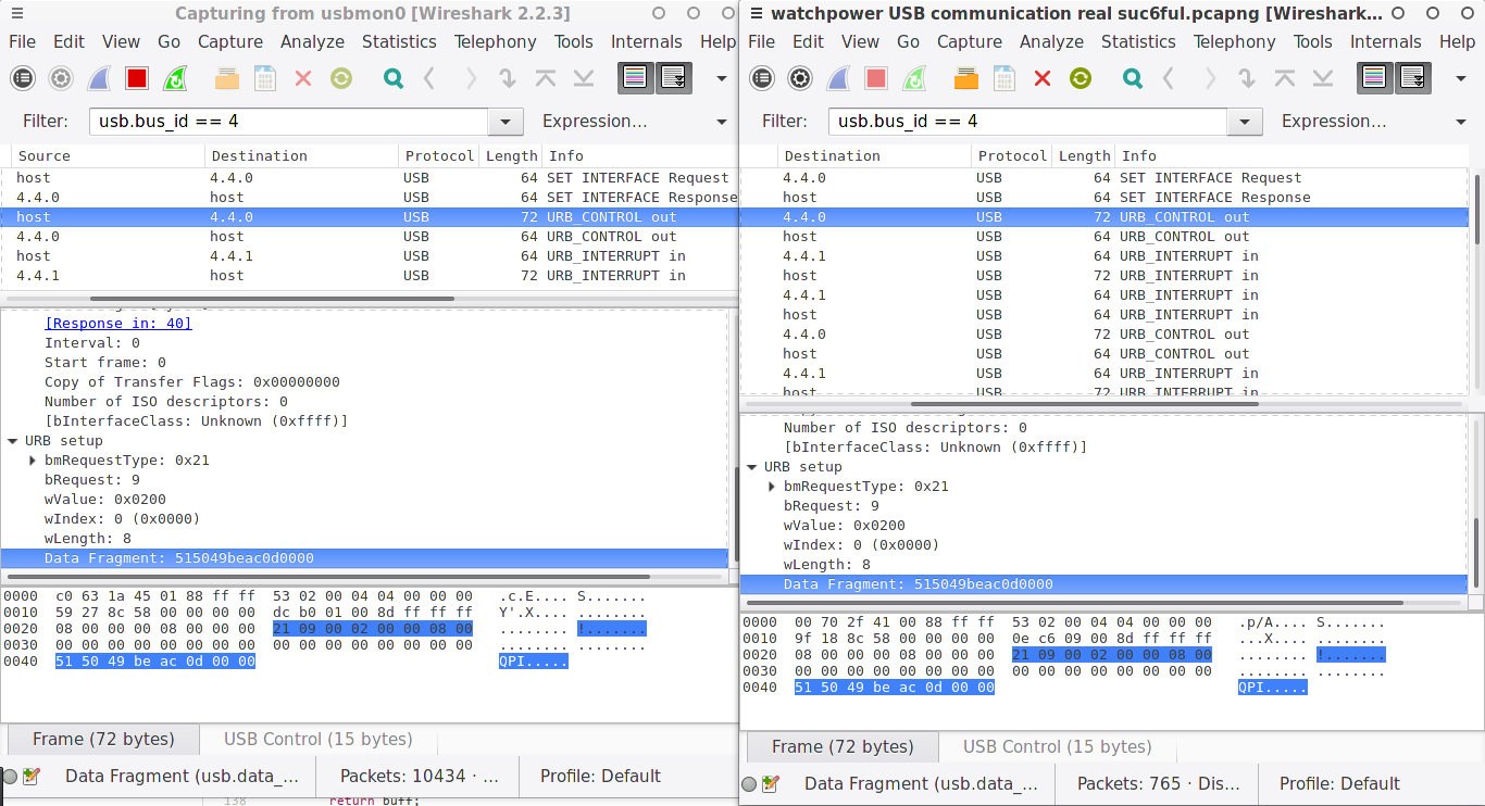
The Data Fragment is the real data you are sending in the body of the control request. That is the part that changed for me and I had to figure out myself. Basically for this inverter it consists of a string (QPI in the example), followed by a 2 byte CRC (crc16.crcxmodem in python helped here) and a linefeed character ‘\r’, and then padded with null characters up to 8 bytes. Knowing this, I could send any command to the inverter and get valid data back. In this case, the data comes back through an interrupt message.
So this was the snippet of test code that I wrote that allowed me to send commands to the inverter and get data back:
def getCommand(cmd):
    cmd = cmd.encode('utf-8')
    crc = crc16.crc16xmodem(cmd).to_bytes(2,'big')
    cmd = cmd+crc
    cmd = cmd+b'\r'
    while len(cmd)<8:
        cmd = cmd+b'\0'
    return cmd

def sendCommand(cmd):
    dev.ctrl_transfer(0x21, 0x9, 0x200, 0, cmd)

def getResult(timeout=100):
    res=""
    i=0
    while '\r' not in res and i<20:
        try:
            res+="".join([chr(i) for i in dev.read(0x81, 8, timeout) if i!=0x00])
        except usb.core.USBError as e:
            if e.errno == 110:
                pass
            else:
                raise
        i+=1
    return res

sendCommand(getCommand('QPI'))
res = getResult()
It’s the world’s smallest driver ever, once again standing on the shoulders of giants. Of course I need to now abstract it to a level where I can request specific variables from the inverter, check the integrity of the returned data, which also contains a 2-byte CRC16, etc. But at this point that is a matter of either knowing what the messages and it’s responses mean (which I do) or just repeating the messages yourself using python code and then looking at the returned data and looking at the inverter to see which number means what (a bit less reliable). One tip is to attach a device to the inverter and request all those variables frequently and logging it in a database or CSV file. Looking at the numbers over time, combined with knowledge about the inverter and how they work can get you a long way to figure this out.